Project S.T.L.S.
Introduction
The S.T.L.S. (Safe Traffic Light System) is designed to save lives by decreasing response time of emergency vehicles. The reason we chose this project was because it has real life applications. We had a goal for our Capstone project to recognize a problem in the real world and improve it. This project also allowed the use of the technology we learned at ITT and we were able to apply it to a real-life problem. The application of this project could make a difference to many people because it lowers the response time for emergency vehicles and could potentially save a life.
This streetlight system was designed to give emergency vehicles a clear driving path to improve response time and save lives. A current city intersection can be controlled by a computer system that times the lights or a system that recognizes when a car is at an intersection and responds to a sensor. The circuit we designed runs off a timing system giving all directions of traffic equal amounts of time. In normal driving conditions the current system will give an emergency vehicle and traffic opposing it both green lights. For example, if an emergency vehicle is heading northbound the southbound traffic will also have a green light. The problem occurs when the emergency vehicle needs to make a turn at an intersection. In order to stop from colliding with traffic the emergency vehicle must come to almost a complete stop and wait for traffic to clear the intersection. Many motorists do not hear the sirens or see the emergency vehicle until it is on top of them and they have to get out of the way to let the emergency vehicle pass which also causes delays.
The S.T.L.S. system addresses both issues by stopping all traffic with a red light except the direction the emergency vehicle is heading. The system accomplishes this by sending an infrared signal to the traffic light with a transmitter. There is a receiver circuit on the traffic light that changes the lights to an “emergency state” temporarily interrupting the main timed circuit. Once the emergency vehicle passes the intersection the circuit returns to normal. The system alerts the motorist that an emergency vehicle is behind them by giving them a different green light. With the S.T.L.S. system the traffic that had a green light will go yellow and then red to stop traffic. The lights that were red will stay red. The direction the emergency vehicle is going will go red and then turn on with a different green to tell motorist that an emergency vehicle is coming and to clear the path. Now the emergency vehicle only has to worry about the vehicles in front of it and not worry about hitting oncoming traffic head on at an intersection while making a turn as they did in the old system. The bottom line is the S.T.L.S. system will save emergency vehicles time spent at busy intersections by clearing a path.
Project Description
Main Circuit
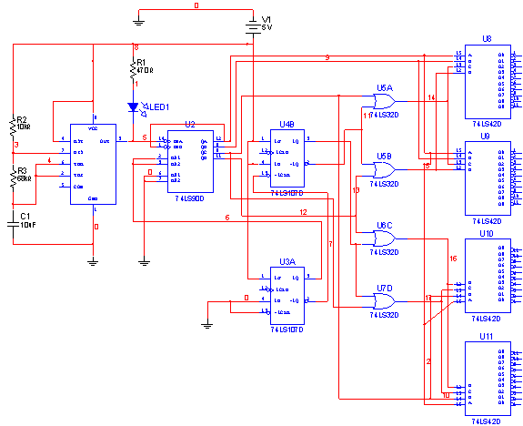
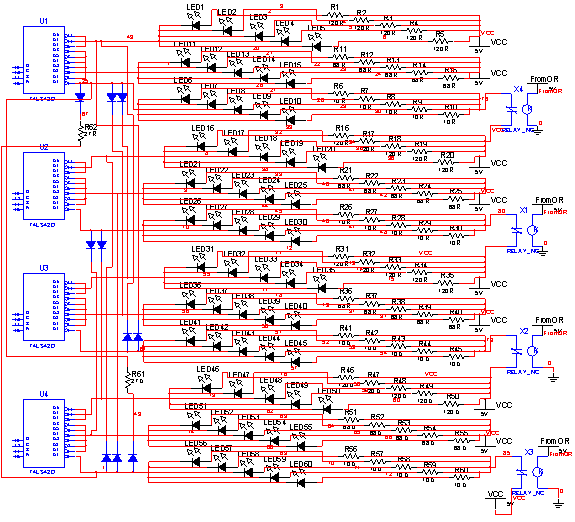
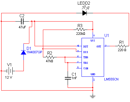
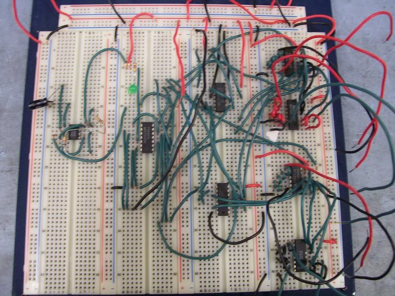
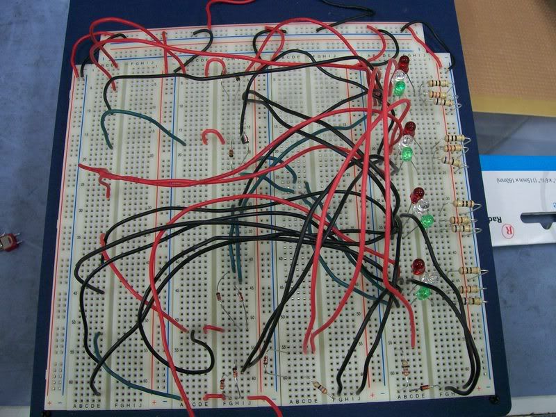
Our main traffic light circuit controls four different directions of travel and cycles from green to red with both reds on for one second before going back to green. We accomplished this by locating a circuit online and modifying it to do what we need. The circuit uses a 555 timer to time the circuit. We decided that a twenty second overall cycle would be sufficient for demonstration. The East and West green lights are on for six seconds, the yellow lights for three seconds, the red lights in all four directions for one second, the North and South directions turn green for six seconds, the yellow lights for three seconds, and then all four directions red for one second before starting the cycle again. The output off the 555 timer feeds a 74LS90 decade counter. This IC counts in binary form from zero to fifteen with every input clock pulse. The outputs from the decade counter go to all four of the 7443 IC’s which control the lights, four OR gates and a J-K flip-flop. The 7443 IC’s are Johnson counters that convert a binary input to a decimal output. We are using these to control our lights. We connected output one to a red light, outputs two through seven to green lights and outputs eight through ten to yellow lights. The inputs to these IC’s come from the decade counter and the OR gates. The J-K flip-flop and the OR gates control the inputs to the 7443’s. This creates disallowed conditions alternately in the 7443’s and prevents any of the outputs from two of the counters going low while the other two counters are in their cycles.
Our first problem arose when we tried building the first circuit we found. The original circuit consisted of only two light segments, one for North and South and one for East and West. We quickly realized this wouldn’t work because we were going to need to control one direction at a time. Our next problem was the hardest problem we came across. The first version of our final design used 73LS145 Johnson counters. We spent four weeks trying to get the outputs to turn on the lights with no success. When we troubleshot the circuit we found that the outputs of the 74LS145 counters were only producing 70 millivolts when off and 23 millivolts when on. According to their specifications they should have been producing five volts when off and zero when on. We were never able to figure out why this was happening but found another Johnson counter, a 7443, that performed the exact same function. When we substituted the 7443’s into the circuit the entire circuit worked perfectly.
The next problem occurred when we tried to get all four red lights on together before cycling back to a green. We are using diodes to turn the red lights on when a green or yellow is on in the other directions. When the circuit would run we would get a yellow and red light on in the same direction. This was happening because when a red light would come on there would still be one volt across the yellow light in the same direction which is enough to turn it on. We fixed this by placing a resistor in series with the diodes tied to the red lights and this dropped the voltage which was going to the yellow lights.
Transmitter/Receiver Circuit
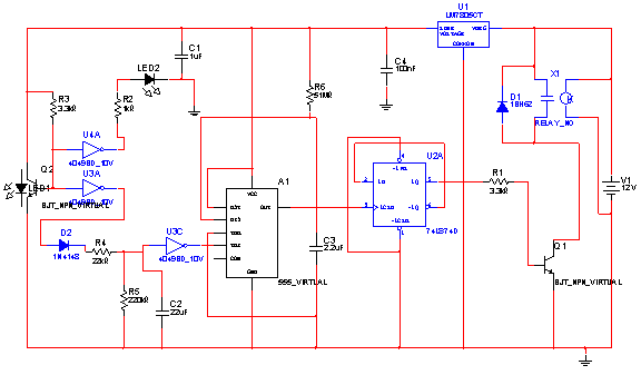
All modern IR remote control devices produce a continuous coded stream of pulses at 37.9 kHz when any button on the module is pressed. These IR pulses are detected and decoded by a receiver (your TV, VCR, etc.) and the appropriate function activated. In our detector the coded stream is converted into a single pulse and that single pulse is used to toggle a relay on & off and the coded information is lost. Only the fact that a button was pressed on your remote control unit is detected. This single pulse is then used to toggle the output of a flip-flop. A high on the /Q output of the flip-flop turns on transistor Q3 which in turn operates the relay and the LED. The LED provides visual indication that the relay is operating.
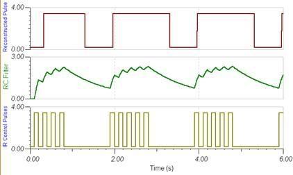
IC1 is an Infra Red module. IR modulated pulses are received and buffered by this IC. It has a standard TTL output; the output with no signal is logic 1. One gate of a CMOS inverter drives Red LED1 as a visible switching aid. Another gate buffers the signal and applies it to the time constant circuit, comprising of R3, C2, R4 and D1. C2 charges via R3, and discharges via R4, D1 prevents quick discharge via the low output impedance of the CMOS buffer. The pulses are further buffered and contain "jagged edges" as shown in appendix B4. These edges are produced by the modulated IR data which has to be removed. This is achieved using IC3, a 555 timer wired as a monostable, with a pulse duration of R5, C4. These cleanly reconstruct a single pulse to activate the bistable latch. A D type flip flop, IC4, is configured as a bistable. The input is applied to the clock pin, the inverted output fed back to the data input and the clear and preset lines are tied to ground. For every pulse the relay will operate. The output pulse is set at about 1.5 seconds and input delay by R3, C2 set at two seconds.
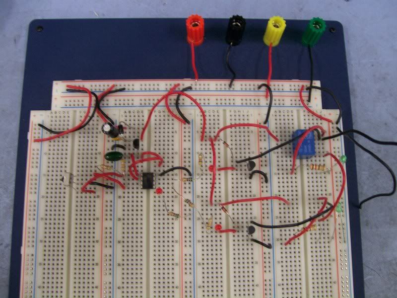
We first started with a simple receiver circuit which did not require as many components as the one we are now using. When we started building this circuit we started running into many problems, but the most significant one was our range. The range was extremely short, only about 3 inches. We tried substituting the resistor and capacitor values, added photo transistors in series and in parallel and tried different transmitters but everything failed to increase the range in our setup.
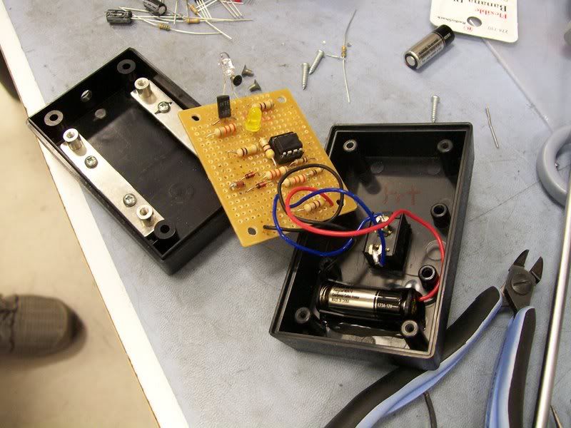
After trying everything possible to fix the other circuit, we decided to try a different one. With this new circuit, building it and troubleshooting it was fairly simple. We ran into the basic problems but after we checked that all components were in their correct position, the orientation of the electrolytic capacitors, the connection of the transistors, diodes, Zener diode and the IC were correct, our circuit was working perfect and range was around 15 feet.
Control Circuit
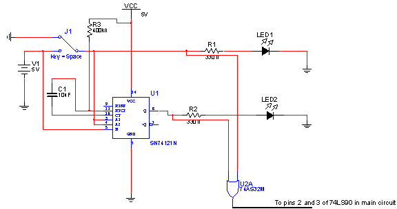
Our control Circuit went through two different designs. The first circuit was successfully built and tested on Multisim but would not work when built on a breadboard. We attempted to troubleshoot the circuit but could not figure out what the problem was. It was designed with more components than necessary and used a CMOS (complementary metal oxide semiconductor) IC to control the lights. Since all of our other IC’s were TTL (transistor-transistor logic) we decided to try a different design and use a TTL IC. We finally decided on a circuit utilizing a one-shot. When the receiver is on it produces five volts which turns on the green emergency light and also produces a five volt pulse to the input of the one-shot. After the emergency vehicle passes and the receiver turns off, the green light turns off and the five volt pulse at the input of the one-shot goes to zero. This causes a negative edge trigger on the one-shot and it produces a five volt output for a predetermined amount of time. We chose three seconds because that is how long our main light circuit keeps the yellow light on in normal operation before switching to red. The anodes of both the green and yellow emergency lights are connected to the inputs of a two input OR gate. The output of the OR gate is high (five volts) whenever the green or yellow emergency light is on and goes to the main light circuit to force all four directions red.
Our main problem with the control circuit was getting it to not only force all directions red but also getting it to turn off the red light in the direction the emergency vehicle is traveling. We accomplished this by using a five volt relay in the normally closed configuration. The relay is connected between the five volt supply and the red light. When the receiver would turn on it would cause the switch to open and remove the five volts from the red light causing it to turn off. When the control circuit turns off it causes the relay to switch closed again and the main circuit returns to its normal function.
Recommendations
This project was a difficult one to master, the digital circuitry used required a great deal of thought to integrate. The same process could have been easily handled by a computer program and programmable logic, but our intention was to make this system easily deployable by any city, not just larger metropolitan ones like
We would also recommend implementing a crosswalk portion in the project. Nearly every intersection has a crosswalk for pedestrians. When an emergency vehicle approaches the lights will not change until the crosswalk portion has completed its cycle. Since pedestrians have the right of way no matter what we wish we could have included this in our project but we were limited on time and resources. We also wish we could have included a turn signal with the main light circuit but again, we were limited on time.
Conclusion
The current system in use today has saved many lives and yet every year the people we rely on most to come to our aid become victims themselves while trying to reach us or stop criminals from causing any more harm. This system is intended to be employed in emergency vehicles such as ambulances and fire trucks but can also be used by the police department. More often than not we see videos of people trying to outrun the police and create an accident in the process. Infra Red signals can propagate great distances allowing them to trigger a light from up to a quarter of a mile away and giving ample time for innocent motorists to clear the intersection and allow the police to do their job without added risk to life and property. The beauty of this system is that it can be installed in most cities without a large initial cost. Larger metropolitan cities like
RECIEVER CIRCUIT
TRANSMITTER
MAIN CIRCUIT
MAIN CIRCUIT WITH LIGHTS
Acknowledgements
I would like to thank Mr. Toussaint. You have been a great teacher and mentor for more than a year and your knowledge seems to know no bounds. Thank you for motivating and pushing me every day. I would like to thank my wife. You have been extremely patient with me for three and a half years. Without your support I wouldn’t be who I am today. I would like to thank my son. All this work and time away was so that I can provide a better life for you. I would like to thank Bill, Roberto and Roger. Without your combined efforts on this and other projects I would have failed miserably.
-Louis Larsen
First of all I’d like to thank my family, especially my dad who always believed in me, and supported me all the way, but how can I forget mom that without her perseverance I would’ve never finished my education.
Throughout my education I’ve run into many different types of teachers, some have helped me, others have held me back. Mr. Toussaint is one of those teachers who will do anything in his power to help you or challenge you, but most importantly he helped me learn and gave me great advice to overcome my problems, so I’d like to thank him for all his help and for standing by me even though many times I let him down by being late or absent to class.
I would also like to thank my classmates, Bill who patiently helped me finished my homework and labs, Roger who made my classes shorter with his jokes, and Louis who I got to know this last quarter and realized how cool he was as well as always setting an example for all of us even though we never followed.
-Roberto Miranda
I would like to thank God, my family, Mr. Toussaint, and my classmates, Louis, Roberto and Bill. Thanks to everyone for the support and encouragement. Without everyone’s support I would not have succeeded in reaching my goal.
-Roger Norsworthy
I would like to thank God for granting me the strength and patience to complete a monumental task such as this project and the Bachelors program in engineering. To my wife Misty for sacrificing just as much of her time to this endeavor as I have and being patient with me as I spent time away while she had to play both roles in the house. To my children, who at times may have felt neglected of my attention when I told them I needed to complete my homework instead of going to the park and play. To the United States Navy and Universal Avionics for offering not only time but experience that allowed me to complete this program. Last, but certainly not least, my fellow classmates who put up with my endless questions, concerns and general demeanor for almost two years, I appreciate all of you greatly. Louis who helped with my usually last minute homework questions to Roger listening to me complain and Roberto for teaching an old dog new tricks with Commsim and Multisim. Without you I would never have made it. I thank you all from the bottom of my heart.
-William Lancaster
No comments:
Post a Comment